The ring die is the most critical and cost-intensive component in any pellet mill, functioning as the heart of the pelleting process by defining pellet quality, production throughput, energy consumption, and operating cost per ton. Every variable in the pelleting process — raw material composition, moisture content, conditioning temperature, roller pressure, and die speed — ultimately expresses itself in the performance and wear life of the ring die. For manufacturers in feed, biomass, wood, and aquaculture pelleting, understanding the engineering principles behind ring die design, material selection, hole geometry, compression ratio, and maintenance is not an academic exercise but a direct determinant of profitability. This guide examines the science and practice of pellet mill ring dies in the depth that serious manufacturers require.
The Functional Role of the Ring Die in Pelleting
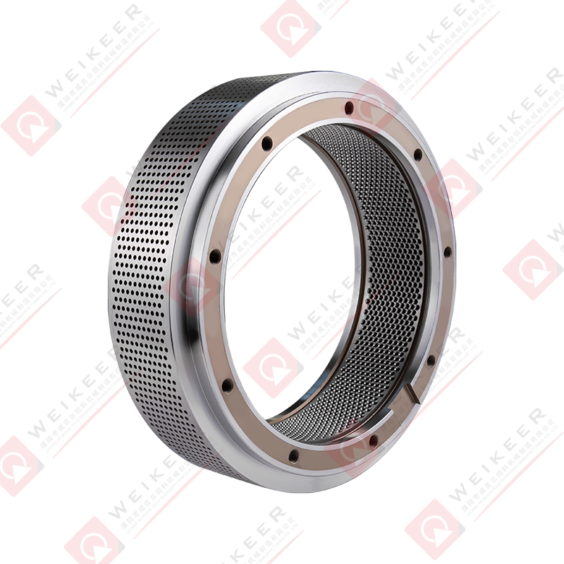
In a ring die pellet mill, the die is a thick-walled cylindrical steel ring perforated with hundreds or thousands of precisely drilled radial holes through which conditioned mash is forced by rotating press rollers. As the rollers travel around the inside of the rotating die, they press the material into the die holes with sufficient force to overcome the friction and compression resistance within the die channel, extruding a continuous column of compacted material that is cut to pellet length by external knives as it exits the outer die surface. The die simultaneously performs multiple functions: it provides the compression channel geometry that determines pellet hardness and density, it controls the throughput rate through its open surface area, it generates and manages the frictional heat that contributes to pellet binding, and it withstands the enormous mechanical and thermal stresses produced by continuous high-pressure operation.
The interaction between the ring die and the press rollers is governed by a narrow set of operating parameters that must remain in balance for efficient pelleting. The roller gap — the clearance between the roller surface and the inner die bore — must be calibrated precisely: too tight and the die and rollers wear rapidly through metal-to-metal contact; too loose and the material slips rather than being forced into the die holes efficiently, reducing throughput and increasing energy consumption. The optimal roller gap is typically in the range of 0.1–0.3 mm for most feed and biomass applications, adjusted for material characteristics and die specifications.
Ring Die Geometry: Hole Design Parameters That Determine Performance
The geometry of the die holes — including their diameter, effective length, inlet configuration, and surface finish — is the primary engineering variable through which die manufacturers control pellet quality and production behavior. Each geometric parameter has a direct, quantifiable effect on pellet characteristics and die performance.
Hole Diameter and Pellet Size
The die hole diameter defines the nominal diameter of the produced pellet, though the actual pellet diameter is typically 5–10% smaller than the hole diameter due to elastic springback of the material after extrusion. Standard die hole diameters in animal feed production range from 1.5 mm for fine aquaculture diets to 12 mm for cattle and equine feeds, while biomass and wood pellet dies typically use 6 mm or 8 mm holes to meet EN 14961 and other fuel pellet standards. Smaller hole diameters require higher compression forces per unit area, generate more heat, and wear more rapidly than larger diameters, which is why fine aquaculture dies command premium prices and require careful material and hardness specification to achieve acceptable service life.
Effective Length and the Compression Ratio
The effective length of a die hole — the portion of the hole through which material is actively compressed — is the most important single parameter controlling pellet hardness, durability, and production resistance. The compression ratio, defined as the ratio of effective length to hole diameter (L/D ratio), is the standardized expression of die resistance used universally in the industry. A die with a 4 mm hole diameter and 32 mm effective length has an L/D ratio of 8:1. Higher L/D ratios produce harder, denser pellets with greater durability but require more energy per ton and generate more heat, while lower L/D ratios produce softer pellets with higher throughput and lower energy consumption. Selecting the correct L/D ratio for a given formulation is one of the most consequential decisions in die specification, and errors in either direction result in either unacceptable pellet quality or unnecessary production costs.
Inlet Configurations: Countersink and Taper Designs
The configuration of the hole inlet — the entry point on the inner bore of the die — significantly affects how material enters the compression channel and how the die wears over time. A straight cylindrical hole with no inlet modification provides maximum effective length but can experience bridging and non-uniform material entry. A countersink inlet — a conical recess machined at the hole entry — funnels material more smoothly into the compression channel, reducing the tendency for material to bridge across the inlet and improving the consistency of filling across all die holes. Relief configurations on the outlet side — a short section of larger diameter at the exit — reduce exit resistance slightly and can help with pelleting materials that tend to crack or crumble at the die exit. The specific inlet and outlet geometry selected should be matched to the material characteristics and the target pellet quality.
Steel Grades and Heat Treatment for Ring Die Manufacturing
The steel used to manufacture ring dies must simultaneously provide high surface hardness to resist abrasive wear in the die holes, sufficient core toughness to withstand the cyclic bending stresses imposed by roller loads, dimensional stability under thermal cycling, and corrosion resistance adequate for the moisture-rich pelleting environment. No single steel grade optimizes all of these properties simultaneously, which is why die manufacturers offer multiple material options and why the correct steel selection is application-dependent.
| Steel Grade |
Surface Hardness (HRC) |
Key Properties |
Best Applications |
| X46Cr13 (4Cr13) |
48 – 52 |
Good corrosion resistance, moderate hardness |
Poultry feed, aquaculture, wet formulations |
| X90CrMoV18 (9Cr18Mo) |
58 – 62 |
High hardness, excellent wear resistance |
Abrasive feeds, mineral-rich formulations |
| 20CrMnTi (Alloy Case Hardened) |
58 – 62 (surface) |
Hard surface, tough core, good fatigue life |
General feed, ruminant, biomass |
| D2 Tool Steel (Cr12MoV) |
60 – 64 |
Very high hardness, superior abrasion resistance |
Wood pellets, highly abrasive biomass |
| 316L Stainless Steel |
25 – 35 |
Maximum corrosion resistance, food-grade |
Pet food, pharmaceutical, specialty feeds |
Heat treatment is as important as base steel selection in determining die performance. Through-hardened dies achieve uniform hardness throughout the wall thickness but may exhibit brittleness at the higher hardness levels. Case-hardened dies — typically produced by carburizing or nitriding — develop a hard wear-resistant surface layer over a tough, ductile core, combining the wear resistance needed at the die hole surface with the fatigue resistance needed in the die body to withstand cyclic roller loading. Nitrided dies achieve particularly high surface hardness with minimal dimensional distortion during the heat treatment process, making them well-suited for precision die geometries.
Compression Ratio Selection Guidelines by Application
Matching the compression ratio to the specific pelleting application is essential for achieving target pellet durability while maintaining acceptable production rates and energy consumption. The following guidelines reflect industry practice across the major pelleting sectors, though optimal values for any specific formulation should be confirmed through trials on the production mill.
- Broiler and poultry feed (high starch, low fiber): L/D ratios of 8:1 to 10:1 are typically sufficient due to the excellent binding properties of starch under steam conditioning, which allows high pellet durability to be achieved at moderate compression ratios without excessive die resistance.
- Ruminant feed (high fiber, coarse ingredients): L/D ratios of 6:1 to 8:1 are commonly used. High fiber content reduces pellet binding, requiring some compression, but excessive L/D ratios with fibrous materials increase the risk of die blockage if throughput is interrupted.
- Aquaculture feeds (fine particle, high durability required): L/D ratios of 10:1 to 14:1 or higher are standard for sinking pellets that must withstand water immersion without disintegration. The high compression requirements of aquaculture dies make steel grade and heat treatment selection particularly critical for achieving acceptable die life.
- Wood and biomass pellets: L/D ratios of 5:1 to 8:1 are typical, though the optimal ratio depends strongly on wood species, particle size distribution, and moisture content. Softwood generally requires lower L/D ratios than hardwood due to its higher lignin softening response to the heat generated in the die.
- Pet food and specialty feeds: L/D ratios are typically in the range of 8:1 to 12:1, with the specific value determined by the fat content of the formulation — high-fat formulations require higher compression ratios to achieve adequate pellet hardness since fat acts as an internal lubricant that reduces binding.
Open Area Ratio and Its Effect on Throughput Capacity
The open area ratio of a ring die — the percentage of the die's working surface area occupied by die holes — directly determines the theoretical maximum throughput capacity of the die. Higher open area means more holes through which material can be extruded per unit time, increasing production capacity. However, the space between holes must be sufficient to maintain structural integrity under the compressive and bending loads imposed during operation. Reducing the inter-hole bridge width below a critical minimum — typically 1.0–1.5 times the hole diameter — risks mechanical failure of the bridges between holes, which manifests as hole deformation, cracking, or catastrophic die failure.
Die designers use finite element analysis (FEA) to optimize hole pattern layouts that maximize open area while maintaining adequate structural safety margins. Staggered hole patterns — where adjacent rows of holes are offset by half a pitch — consistently achieve higher open area ratios than aligned patterns while maintaining better stress distribution in the inter-hole bridges. For a given die diameter and wall thickness, the maximum achievable open area ratio typically falls in the range of 20–35%, with the specific value depending on hole diameter, wall thickness, and bridge width constraints.
Wear Mechanisms and Factors That Shorten Ring Die Service Life
Understanding how ring dies wear — and what operational and material factors accelerate wear — is essential for maximizing die service life and minimizing the cost per ton of pellets produced. Die wear is not a single mechanism but a combination of several distinct degradation processes acting simultaneously.
- Abrasive wear in die holes: The predominant wear mechanism in most applications, caused by hard mineral particles — sand, silica, bone ash, mineral premix components — abrading the die hole surface as material passes through under pressure. Abrasive wear progressively increases hole diameter, reducing pellet density and durability, and eventually requires die replacement when holes have enlarged beyond tolerance.
- Adhesive wear on the inner bore: The inner bore of the die, where rollers make contact with the material bed, wears through a combination of abrasion and adhesion. As the bore wears deeper, effective roller penetration increases and the roller gap must be readjusted. Excessive bore wear eventually reduces the die wall thickness below safe operating limits.
- Corrosive wear from moisture and acids: In steam conditioning systems, high moisture content combined with organic acids naturally present in feed materials creates a mildly corrosive environment at the die surface. Corrosive wear preferentially attacks grain boundaries and softer microstructural constituents, roughening the die hole surface and accelerating subsequent abrasive wear. Stainless steel or high-chromium dies significantly reduce corrosive wear in wet applications.
- Fatigue cracking from cyclic roller loads: Each time a roller passes over a section of the die, it imposes a compressive stress on the inner bore surface that propagates outward through the die wall. Over millions of loading cycles, this cyclic stress can initiate fatigue cracks, particularly at stress concentration points such as the edges of die holes. Proper die hardness, appropriate roller gap setting, and avoiding impact loads from foreign objects in the feed are the primary preventive measures.
- Thermal damage from overheating: Running a die with a blocked or near-blocked hole pattern concentrates frictional heat at specific locations on the die, potentially exceeding the steel's tempering temperature and causing localized softening. Softened zones wear dramatically faster than the surrounding properly hardened steel, creating uneven wear patterns that reduce pellet quality consistency and shorten remaining die life.
Practical Strategies to Maximize Ring Die Service Life
Systematic attention to a set of proven operational and maintenance practices can substantially extend ring die service life beyond what is achievable through die specification alone. These practices address the root causes of premature wear rather than simply replacing dies more frequently.
Correct Die Break-In Procedure
New ring dies require a structured break-in process before being run at full production capacity. The break-in process — typically involving running the die for several hours at reduced feed rate with an oily mash containing coarse grinding to polish and seat the die holes — achieves two important objectives: it removes sharp machining marks from die hole surfaces that would cause abnormally high initial wear, and it establishes a stable, work-hardened surface layer in the die holes that significantly improves subsequent wear resistance. Skipping or abbreviating the break-in process to recover production time is a false economy that measurably shortens overall die life.
Shutdown and Storage Protocols
Ring dies left idle with compressed mash in the holes are vulnerable to a specific and serious failure mode: the mash dries, swells, and expands within the die holes with sufficient force to crack the inter-hole bridges — a phenomenon known as "die blowing." Preventing this requires purging the die with an oil-sand mixture at the end of every production run to displace feed material from the holes before shutdown. Dies stored for extended periods should be coated internally and externally with a corrosion inhibitor and stored in a dry environment away from temperature extremes that could cause condensation cycles on the die surface.
Foreign Object Prevention and Feed Preparation
Metal contamination in the feed stream is one of the most damaging events a ring die can experience. A single bolt, nut, or piece of wire entering the pellet mill can crack the die, damage the rollers, and require both components to be replaced simultaneously at very high cost. Installing and regularly maintaining magnetic separators and screening equipment upstream of the pellet mill, combined with regular inspection of feed handling equipment for loose or deteriorating metal parts, is the most cost-effective die protection measure available. Dedicated pellet mill safety filters that automatically reject oversized particles and tramp metal should be considered standard equipment rather than optional enhancements in any serious production facility.
Evaluating Ring Die Performance: Key Metrics for Manufacturers
Manufacturers who track die performance systematically rather than simply replacing dies when they fail are better positioned to optimize die specifications, identify operational problems early, and accurately calculate the true cost per ton of production. The following metrics provide a comprehensive performance picture when tracked consistently across die service life.
- Tons produced per die (total lifetime tonnage): The fundamental measure of die service life, enabling direct cost-per-ton calculation and comparison between different die suppliers, steel grades, and formulations. Tracking this metric over a statistically meaningful sample of die lives reveals trends and identifies outlier events that warrant investigation.
- Pellet Durability Index (PDI) versus die age: Monitoring PDI at regular intervals throughout a die's service life reveals the point at which hole wear has progressed sufficiently to reduce pellet quality below acceptable thresholds. This allows proactive die replacement scheduling rather than reactive replacement after quality failures have already affected finished product.
- Specific energy consumption (kWh per ton): Energy consumption per ton of pellets produced increases as die holes wear and surface roughness increases, requiring more force to extrude material at the same rate. A rising specific energy trend with constant formulation and die speed is a reliable early indicator of die wear that should trigger inspection and planning for die replacement.
- Die hole diameter measurements at retirement: Measuring a representative sample of die holes at the point of retirement — using precision plug gauges or optical measurement — establishes the actual wear rate and allows prediction of remaining life in future dies based on early-life measurements, enabling more accurate die replacement scheduling and budget forecasting.


 русский
 Español
 عربى
عربى 中文简体
中文简体


